Part 1 of this series focussed on the interface MTU configuration, looking how different vendors implement the setting. Some include the layer 2 headers, some don’t. Part 2 looked at Jumbo Frames, IP MTU and OSPF. In this post we’ll build a simple 4 node MPLS network and check out how the default MTU settings affect the transmission of data. We’ll also enable a couple of 802.1q tagged interfaces. The configuration will be adjusted accordingly to enable the transmission of 2000 bytes of IP payload across the MPLS core.
802.1q Frame
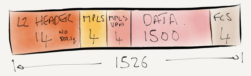
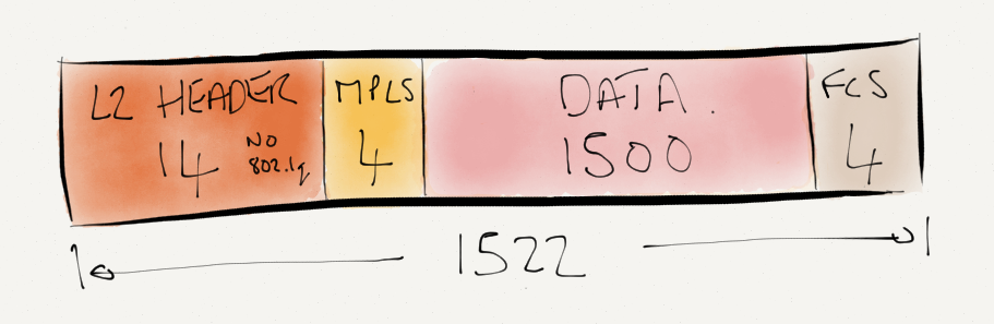
First of all a quick refresher on what an Ethernet frame looks like if it contains an 802.1q tag in the header. 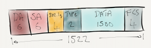 802.1q does not encapsulate the Ethernet frame, simply a new 4 byte header is inserted between the source MAC address and the Ethertype. Now with 1500 bytes payload, the frame size has increased to 1522 bytes (1518 not counting the FCS). The 802.1q tag consists of the following fields:
- TPID: Tag Protocol ID. A 16-bit field with a value set to 0x8100 to identify the frame as IEEE 802.1q tagged
- Priority. A 3 bit field which refers to the IEEE 802.1p priority. i.e. class of service
- DEI: Drop eligible indicator. Used to indicated if frames can be dropped.
- VID: VLAN ID. A 12-bit field specifying the VLAN.
Multiple 802.1q tags can be present in the frame. This is known as IEEE 802.1ad Q-inQ. More on this another time.
MPLS Frame
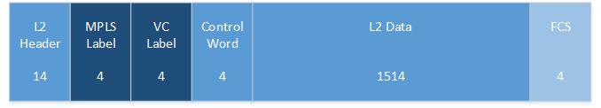
Also let’s take a look at an Ethernet Frame containing an MPLS header.  The 32-bit MPLS label is inserted between the L2 header and the protocol data. This is why it’s sometimes called a shim header. The ethertype is set to 0x8847 to identify the payload as MPLS. The MPLS label contains the following fields:
- Label. The label itself – 20 bits.
- EXP. A 3-bit field used for QoS markings.
- S. 1-bit to represent if a label is the last in the stack.
- TTL. An 8-bit time to live field.
As the S bit implies, there can be a stack of labels. More on this another time.
Lab
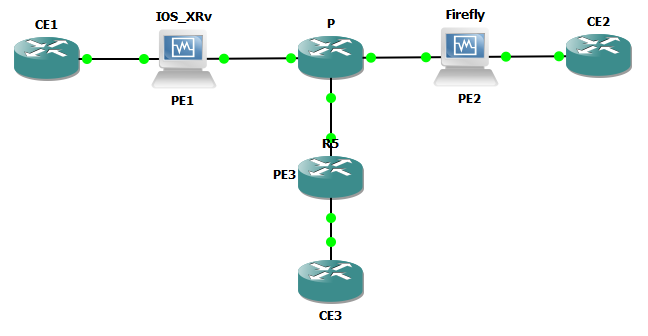
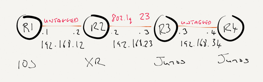
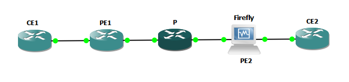
For this lab, I’ll be using the topology below. We’ll start with a base IP/OSPF configuration and add MPLS. MTUs will be adjusted to enable a 2000 byte MPLS payload to be transmitted across the topology. 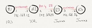 Software revisions are as follows
- IOS (Cisco 7200 12.4(24)T)
- IOS-XR (IOS-XRv 5.1.1)
- Junos (Olive 12.3R5.7)
R1 is running IOS, the base configuration is as below.
interface Loopback0
 ip address 1.1.1.1 255.255.255.255
!
interface GigabitEthernet1/0
 ip address 192.168.12.1 255.255.255.0
 ip ospf network point-to-point
 negotiation auto
!
router ospf 1
 log-adjacency-changes
 network 1.1.1.1 0.0.0.0 area 0
 network 192.168.12.1 0.0.0.0 area 0
!
MTUs are at the defaults
R1#show interfaces g1/0 | i MTU
  MTU 1500 bytes, BW 1000000 Kbit/sec, DLY 10 usec,
R1#show ip interface g1/0 | i MTU
  MTU is 1500 bytes
R2 is running IOS-XR with a configuration as below
interface Loopback0
 ipv4 address 2.2.2.2 255.255.255.255
!
interface GigabitEthernet0/0/0/0
!
interface GigabitEthernet0/0/0/0.23
 description Link to R3
 ipv4 address 192.168.23.2 255.255.255.0
 encapsulation dot1q 23
!
interface GigabitEthernet0/0/0/1
 description Link to R1
 ipv4 address 192.168.12.2 255.255.255.0
!
router ospf 1
 area 0
  interface Loopback0
   passive enable
  !
  interface GigabitEthernet0/0/0/0.23
   network point-to-point
  !
  interface GigabitEthernet0/0/0/1
   network point-to-point
  !
 !
!
There is nothing special about the link from R1 to R2, the MTU is set to the default 1514, so we can expect 1500 to be the IP MTU. Notice that the link from R2 to R3 is an 802.1q tagged interface.
XR has automatically increased the MTU on the 802.1q subinterface to 1518, to keep 1500 bytes available to IP.
RP/0/0/CPU0:R2-XRv#show ipv4 interface GigabitEthernet0/0/0/0.23 | i MTU
  MTU is 1518 (1500 is available to IP)
Here is the Junos configuration on R3.
interfaces {
    em0 {
        vlan-tagging;
        unit 23 {
            vlan-id 23;
            family inet {
                address 192.168.23.3/24;
            }
        }
    }
    em1 {
        unit 0 {
            family inet {
                address 192.168.34.3/24;
            }
        }
    }
    lo0 {
        unit 0 {
            family inet {
                address 3.3.3.3/32;
            }
        }
    }
}
protocols {
    ospf {
        area 0.0.0.0 {
            interface lo0.0 {
                passive;
            }
            interface em0.23 {
                interface-type p2p;
            }
            interface em1.0 {
                interface-type p2p;
            }
        }
    }
}
On the tagged interface to VLAN23, Junos has also increased the MTU to 1518 to accommodate the VLAN tag and enable 1500 bytes of protocol data. Note, if you configure the interface MTU manually or XR or Junos you’d still need to allow for the dot1q tags.
matt@R3-Junos> show interfaces em0 | match "Phy|Log|MTU|Tag"
Physical interface: em0, Enabled, Physical link is Up
  Type: Ethernet, Link-level type: Ethernet, MTU: 1518
  Logical interface em0.23 (Index 65) (SNMP ifIndex 506)
    Flags: SNMP-Traps VLAN-Tag [ 0x8100.23 ]  Encapsulation: ENET2
    Protocol inet, MTU: 1500
I like it how Junos includes the VLAN Tag 0x8100.23 in the output to indicate a 802.1q tag 23.
Jumping over to R4, the configuration is as below
interfaces {
    em1 {
        unit 0 {
            family inet {
                address 192.168.34.4/24;
            }
        }
    }
    lo0 {
        unit 0 {
            family inet {
                address 4.4.4.4/32;
            }
        }
    }
}
protocols {
    ospf {
        area 0.0.0.0 {
            interface lo0.0 {
                passive;
            }
            interface em1.0 {
                interface-type p2p;
            }
        }
    }
}
The MTU will be 1514 for the Physical, and 1500 for family inet.
matt@R4-Junos> show interfaces em1 | match "Phy|Log|MTU"
Physical interface: em1, Enabled, Physical link is Up
  Type: Ethernet, Link-level type: Ethernet, MTU: 1514
  Logical interface em1.0 (Index 69) (SNMP ifIndex 24)
    Protocol inet, MTU: 1500
At this point the biggest ping that we’ll be able to get from R4 to R1’s loopback address 1.1.1.1 is going to be 1472, representing 1500 byes of IP data and 1514 on the wire (1472 data + 8 ICMP header + 20 IP header + 14 Ethernet).
matt@R4-Junos> ping rapid do-not-fragment count 1 size 1472 1.1.1.1
PING 1.1.1.1 (1.1.1.1): 1472 data bytes
!
--- 1.1.1.1 ping statistics ---
1 packets transmitted, 1 packets received, 0% packet loss
round-trip min/avg/max/stddev = 14.124/14.124/14.124/nan ms
MPLS
MPLS and will now be enabled across the topology. LSPs will be RSVP signalled and I’ll demonstrate how the MTU settings need to be updated. As this post is focussing on the approach different vendors take to MTU, I’ll skip the MPLS detail and save it for another time, but the relevant MPLS config is below.
On R1 I’ve enabled a Tunnel interface and statically routed IP traffic to R4’s Loopback via this MPLS TE tunnel. LDP has not been enabled and doesn’t need to be.
mpls traffic-eng tunnels
!
interface Tunnel0
 ip unnumbered Loopback0
 tunnel destination 4.4.4.4
 tunnel mode mpls traffic-eng
 tunnel mpls traffic-eng path-option 1 dynamic
 no routing dynamic
!
interface GigabitEthernet1/0
 mpls traffic-eng tunnels
!
router ospf 1
 mpls traffic-eng router-id Loopback0
 mpls traffic-eng area 0
!
ip route 4.4.4.4 255.255.255.255 Tunnel0
R2. In IOS-XR, the interfaces are added to the protocol.
router ospf 1
 area 0
  mpls traffic-eng
 !
 mpls traffic-eng router-id Loopback0
!
rsvp
 interface GigabitEthernet0/0/0/1
 !
 interface GigabitEthernet0/0/0/0.23
 !
!
mpls traffic-eng
 interface GigabitEthernet0/0/0/1
 !
 interface GigabitEthernet0/0/0/0.23
R3. On Junos we add the Interfaces to the protocols MPLS and RSVP and enable family mpls on the logical unit.
interfaces {
    em0 {
        unit 23 {
            family mpls;
        }
    }
    em1 {
        unit 0 {
            family mpls;
        }
    }
}
protocols {
    rsvp {
        interface em0.23;
        interface em1.0;
    }
    mpls {
        interface em0.23;
        interface em1.0;
    }
    ospf {
        traffic-engineering;
    }
}
R4. I’ve created a dynamic label switched path to R1. This path gets installed in table inet.3 but as inet.3 is only used for BGP next hops by default, my traffic test from R4 to 1.1.1.1 won’t be labelled. I want to keep this lab simple, so I’ve used traffic-engineering mpls-forwarding to ensure that the LSP to 1.1.1.1 is placed in to table inet.0
interfaces {
    em1 {
        unit 0 {
            family mpls;
        }
    }
}
protocols {
    rsvp {
        interface em1.0;
    }
    mpls {
        traffic-engineering mpls-forwarding;
        label-switched-path R4toR1 {
            to 1.1.1.1;
        }
        interface em1.0;
    }
    ospf {
        traffic-engineering;
    }
}

matt@R4-Junos> show route table inet.0 1.1.1.1

inet.0: 9 destinations, 11 routes (9 active, 0 holddown, 0 hidden)
@ = Routing Use Only, # = Forwarding Use Only
+ = Active Route, - = Last Active, * = Both

1.1.1.1/32         @[OSPF/10] 00:09:15, metric 4
                    > to 192.168.34.3 via em1.0
                   #[RSVP/7/1] 00:05:45, metric 4
                    > to 192.168.34.3 via em1.0, label-switched-path R4toR1
OK, so this point we have a functioning MPLS topology with traffic from R1 to R4 (4.4.4.4) and from R4 to R1 (1.1.1.1) being label switched.
R1#traceroute 4.4.4.4

Type escape sequence to abort.
Tracing the route to 4.4.4.4

  1 192.168.12.2 [MPLS: Label 16000 Exp 0] 32 msec 20 msec 8 msec
  2 192.168.23.3 [MPLS: Label 299824 Exp 0] 8 msec 8 msec 12 msec
  3 4.4.4.4 12 msec 16 msec 8 msec

matt@R4-Junos> traceroute 1.1.1.1
traceroute to 1.1.1.1 (1.1.1.1), 30 hops max, 40 byte packets
 1  192.168.34.3 (192.168.34.3)  1.050 ms  0.863 ms  0.765 ms
     MPLS Label=299792 CoS=0 TTL=1 S=1
 2  192.168.23.2 (192.168.23.2)  5.398 ms  3.393 ms  10.241 ms
     MPLS Label=16001 CoS=0 TTL=1 S=1
 3  192.168.12.1 (192.168.12.1)  10.008 ms  7.667 ms  4.486 ms
The MTU settings are still at the defaults, so let’s see what the maximum size of IP payload we are able to transmit. We know that only one label is in the stack, so will the maximum be 1496?
R1#ping 4.4.4.4 rep 2 df-bit size 1488

Type escape sequence to abort.
Sending 2, 1488-byte ICMP Echos to 4.4.4.4, timeout is 2 seconds:
Packet sent with the DF bit set
!!
Success rate is 100 percent (2/2), round-trip min/avg/max = 12/14/16 ms
R1#ping 4.4.4.4 rep 2 df-bit size 1489

Type escape sequence to abort.
Sending 2, 1489-byte ICMP Echos to 4.4.4.4, timeout is 2 seconds:
Packet sent with the DF bit set
..
Success rate is 0 percent (0/2)

matt@R4-Junos> ping rapid do-not-fragment count 2 size 1460 1.1.1.1
PING 1.1.1.1 (1.1.1.1): 1460 data bytes
!!
--- 1.1.1.1 ping statistics ---
2 packets transmitted, 2 packets received, 0% packet loss
round-trip min/avg/max/stddev = 5.558/6.949/8.340/1.391 ms

matt@R4-Junos> ping rapid do-not-fragment count 2 size 1461 1.1.1.1
PING 1.1.1.1 (1.1.1.1): 1461 data bytes
..
--- 1.1.1.1 ping statistics ---
2 packets transmitted, 0 packets received, 100% packet loss
No, that maximum that could be transmitted in both directions was 1488 bytes of IP data. Don’t forget for Junos, 28 bytes of headers are added to the ping size.
By default Junos derives the MPLS MTU from the Interface settings and makes allowance for 3 labels in the stack, so with a 1500 byte interface MTU, the MPLS MTU would be set to 1488. This is why we can only ping with 1488 bytes of protocol data.
On both of the Junos routers I’m going to go ahead and set the Interface MTU to 9192, but since my goal is to test an MPLS switched payload of 2000 bytes IP data, I’ll set the MPLS MTU and leave the IP MTU at 1500 bytes. Note if the MPLS MTU is user configured then the configured value includes the labels. I’ll set the MPLS MTU to 2004 to allow the 2000 bytes of data and for this test I only need to make allowance for 1 label.
em0 {
    vlan-tagging;
    mtu 9192;
    unit 23 {
        vlan-id 23;
        family inet {
            mtu 1500;
            address 192.168.23.3/24;
        }
        family mpls {
            mtu 2004;
        }
    }
}
em1 {
    mtu 9192;
    unit 0 {
        family inet {
            mtu 1500;
            address 192.168.34.3/24;
        }
        family mpls {
            mtu 2004;
        }
    }
}

matt@R3-Junos> show interfaces em[01]* | match "em|proto"
Physical interface: em0, Enabled, Physical link is Up
  Logical interface em0.23 (Index 72) (SNMP ifIndex 506)
    Protocol inet, MTU: 1500
    Protocol mpls, MTU: 2004, Maximum labels: 3
Physical interface: em1, Enabled, Physical link is Up
  Logical interface em1.0 (Index 65) (SNMP ifIndex 24)
    Protocol inet, MTU: 1500
    Protocol mpls, MTU: 2004, Maximum labels: 3
I love how Junos allows a regexp to be used pretty much however I feel like using it.
At this point the maximum ping size from both sides of the network is currently 1496 bytes. This is as expected because we have 1 label in the stack and the Cisco routers are still set to 1500 bytes on the Interface MTU.
Let’s have a look what’s going on with the interface MTU parameters on the Ciscos.
R1#show mpls interfaces g1/0 detail
Interface GigabitEthernet1/0:
        IP labeling enabled (ldp):
          Interface config
        LSP Tunnel labeling not enabled
        BGP labeling not enabled
        MPLS operational
        MTU = 1500
RP/0/0/CPU0:R2-XRv#show im database interface GigabitEthernet0/0/0/0.23

View: OWN - Owner, L3P - Local 3rd Party, G3P - Global 3rd Party, LDP - Local Data Plane
      GDP - Global Data Plane, RED - Redundancy, UL - UL

Node 0/0/CPU0 (0x0)

Interface GigabitEthernet0/0/0/0.23, ifh 0x00000700 (up, 1518)
  Interface flags:          0x0000000000800597 (ROOT_IS_HW|IFINDEX
                            |SUP_NAMED_SUB|BROADCAST|CONFIG|VIS|DATA|CONTROL)
  Encapsulation:            dot1q
  Interface type:           IFT_VLAN_SUBIF
  Control parent:           GigabitEthernet0/0/0/0
  Data parent:              GigabitEthernet0/0/0/0
  Views:                    UL|GDP|LDP|G3P|L3P|OWN

  Protocol        Caps (state, mtu)
  --------        -----------------
  None            vlan_jump (up, 1518)
  None            spio (up, 1518)
  None            dot1q (up, 1518)
  arp             arp (up, 1500)
  ipv4            ipv4 (up, 1500)
  mpls            mpls (up, 1500)
It would appear that the MPLS MTU is 1500, so straight away we can see that Cisco are including the labels in the 1500, otherwise our ping of 1500 would be working.
Let’s go ahead and check this theory by increasing the Interface MTU and the MPLS MTU by 4 bytes on each Cisco. The IP MTU will remain set at 1500.
R1#show mpls interfaces g1/0 detail | i MTU
        MTU = 1504

RP/0/0/CPU0:R2-XRv#show im database interface GigabitEthernet0/0/0/0.23 | i "ipv4|mpls"
  ipv4            ipv4 (up, 1500)
  mpls            mpls (up, 1504)

R1#ping 4.4.4.4 rep 2 df-bit size 1500

Type escape sequence to abort.
Sending 2, 1500-byte ICMP Echos to 4.4.4.4, timeout is 2 seconds:
Packet sent with the DF bit set
!!
Success rate is 100 percent (2/2), round-trip min/avg/max = 16/16/16 ms

matt@R4-Junos> ping rapid do-not-fragment count 2 size 1472 1.1.1.1
PING 1.1.1.1 (1.1.1.1): 1472 data bytes
!!
--- 1.1.1.1 ping statistics ---
2 packets transmitted, 2 packets received, 0% packet loss
round-trip min/avg/max/stddev = 8.091/9.467/10.844/1.377 ms
The 1500 byte ping now works exactly as expected.
Since my goal is to get a 2000 byte label switched ping working. I’ll go ahead and set the MPLS MTU on the Ciscos for test. I’ll set this to 2004 like I did on the Junos routers.
R1:
interface GigabitEthernet1/0
 mtu 4000
 ip mtu 1500
 mpls mtu 2004
end
R1#show mpls interfaces g1/0 detail | i MTU
        MTU = 2004

R2:
interface GigabitEthernet0/0/0/1
 mtu 9000
 ipv4 mtu 1500
 mpls
  mtu 2004
 !
!
RP/0/0/CPU0:R2-XRv#show im database interface GigabitEthernet0/0/0/0.23 | i "ipv4|mpls"
  ipv4            ipv4 (up, 1500)
  mpls            mpls (up, 2004)
OK so now we have the capability for an MPLS LSP with 2000 bytes payload. But can I ping from R4 to R1 with my 2000 byte ping?
Well actually I can’t.
matt@R4-Junos> ping 1.1.1.1 source 4.4.4.4 do-not-fragment size 1972
PING 1.1.1.1 (1.1.1.1): 1972 data bytes
76 bytes from 192.168.12.2: frag needed and DF set (MTU 1500)
Vr HL TOS  Len   ID Flg  off TTL Pro  cks      Src      Dst
 4  5  00 07d0 186f   2 0000  3e  01 12b5 4.4.4.4  1.1.1.1

^C
--- 1.1.1.1 ping statistics ---
1 packets transmitted, 0 packets received, 100% packet loss
We’re being told that the packet is too big at R2. Why’s this? Well remember that MPLS will pop the label at the hop before the destination. This is known as penultimate hop popping. So the data between R2 is and R1 is transmitted as IP, not MPLS. As I left the MTU at 1500 for IP data, the echo request cannot be transmitted.
I actually did this on purpose by changing the config on R1 so that the LSPs were implicit null signalled. If I go ahead and change the signalling to explicit null, the LSP will then be labelled end to end and the ping will work.
On R1 I turn off implicit-null and R4 I turn on explicit-null.
R1(config)#no mpls traffic-eng signalling advertise implicit-null

matt@R4-Junos# set protocols mpls explicit-null

R1#ping 4.4.4.4 source 1.1.1.1 rep 2 df size 2000

Type escape sequence to abort.
Sending 2, 2000-byte ICMP Echos to 4.4.4.4, timeout is 2 seconds:
Packet sent with a source address of 1.1.1.1
Packet sent with the DF bit set
!!
Success rate is 100 percent (2/2), round-trip min/avg/max = 16/20/24 ms

matt@R4-Junos> ping 1.1.1.1 source 4.4.4.4 do-not-fragment size 1972
PING 1.1.1.1 (1.1.1.1): 1972 data bytes
1980 bytes from 1.1.1.1: icmp_seq=0 ttl=253 time=11.802 ms
^C
--- 1.1.1.1 ping statistics ---
1 packets transmitted, 1 packets received, 0% packet loss
round-trip min/avg/max/stddev = 11.802/11.802/11.802/0.000 ms
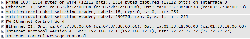
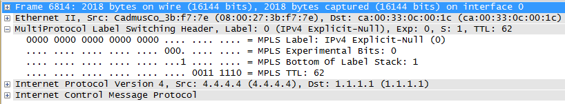
Excellent! The capture below was taken on R2s interface to R1, and you can see the 2018 bytes on the wire (1972 data + 8 ICMP + 20 IP + 4 MPLS + 14 Ethernet). Notice Label 0 is used for Explicit Null on IPv4.

Summary
In this post we focussed on MPLS MTU and how to use MPLS MTU to enable a payload >1500 bytes. I’ve demonstrated the the Interface MTU, MPLS MTU and IP MTU can be set to totally different values.
Why does any of this matter? In a provider core you need to be able to transport your customers full size frames across your network. You can guarantee that customer data will be at least 1500 bytes, but depending on the service specification that you want to sell, could be as large as 9000.
I’ve introduced quite a lot of MPLS terms in this lab. In a later post I will go through this topology again in detail, and talk through the MPLS specifics.
 Software revisions are as follows