Now that we know about IGP based LSP forwarding on Junos, the 2nd part in this series focuses on BGP and table inet.3.
We also continue from where part 1 left off, by looking at how traffic-engineering bgp-igp and mpls-forwarding can affect route redistribution from OSPF into BGP.
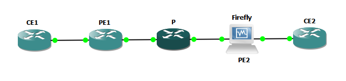
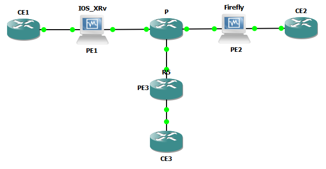
Lab Topology
For this lab, I’ll be using the topology below.
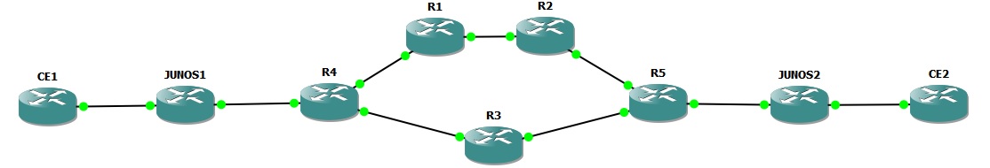
Software revisions are as follows
- CE Routers (CE1, CE2): IOS (Cisco 7200 12.4(24)T)
- P Routers (R1, R2, R3, R4, R5): IOS (Cisco 7200 12.4(24)T)
- PE Routers (Junos1, Junos2): Junos (Olive 12.3R5.7)
As with Part 1, the base configurations are using OSPF as the routing protocol and LDP to exchange transport labels.
Route redistribution (bgp-igp and mpls-forwarding)
Here’s what I changed on Junos 1. The OSPF route 102.102.102.102 learnt via OSPF from CE2 will be redistributed in to BGP.
By the way, I’m not suggesting that your CEs should be part of your core IGP, but for the purposes on this lab test… 🙂
root@R6-Junos1# show | compare
[edit protocols bgp group internal]
+    export ospf2bgp;
[edit policy-options]
+   policy-statement ospf2bgp {
+       from {
+           protocol ospf;
+           route-filter 102.102.102.102/32 exact;
+       }
+       then accept;
+   }
The configuration on Junos1 is still running with “traffic-engineering mpls-forwarding” so the routing table has OSPF as the active route for routing, and the LDP route is active for forwarding
root@R6-Junos1> show route 102.102.102.102

inet.0: 21 destinations, 35 routes (21 active, 0 holddown, 0 hidden)
@ = Routing Use Only, # = Forwarding Use Only
+ = Active Route, - = Last Active, * = Both

102.102.102.102/32 @[OSPF/150] 00:00:28, metric 0, tag 0
                    > to 192.168.46.4 via em0.0
                   #[LDP/9] 00:00:28, metric 1
                    > to 192.168.46.4 via em0.0, Push 28
Hence you would definitely expect the routing policy to match on the OSPF route 102.102.102.102 and therefore we’ll see the route in BGP right? Sure enough if I hop over to Junos2, the route is there:
root@R7-Junos2> show route receive-protocol bgp 6.6.6.6

inet.0: 22 destinations, 23 routes (22 active, 0 holddown, 0 hidden)
  Prefix                  Nexthop              MED     Lclpref    AS path
  102.102.102.102/32      192.168.46.4         0       100        I
OK show what happens if I change over to traffic-engineering bgp-igp on Junos1? The LDP route becomes the active route for routing and forwarding, and isn’t matched by my policy, so is not advertised to Junos2.
inet.0: 22 destinations, 36 routes (22 active, 0 holddown, 0 hidden)
@ = Routing Use Only, # = Forwarding Use Only
+ = Active Route, - = Last Active, * = Both

102.102.102.102/32 *[LDP/9] 00:00:04, metric 1
                    > to 192.168.46.4 via em0.0, Push 28
                    [OSPF/150] 00:04:54, metric 0, tag 0
                    > to 192.168.46.4 via em0.0

root@R7-Junos2> show route receive-protocol bgp 6.6.6.6

inet.0: 22 destinations, 22 routes (22 active, 0 holddown, 0 hidden)

inet.3: 14 destinations, 14 routes (14 active, 0 holddown, 0 hidden)
BGP (LSP forwarding) and table inet.3
We’ll now have a look at how BGP operates. I’ve set the “traffic-engineering” on Junos1 back to the defaults. We should expect BGP to recursively resolve it’s next-hop via inet.3 and therefore MPLS route the traffic. Let’s see!
iBGP Peering
There is an iBGP peering session between Junos1 and Junos2. No other routers are running iBGP
eBGP Peering
Junos2 has an eBGP peering with CE1. CE has a second Loopback 112.112.112.112 being advertised via this eBGP session.
root@R7-Junos2> show configuration protocols bgp
group as102 {
    peer-as 102;
    neighbor 192.168.102.1;
}
group internal {
    local-address 7.7.7.7;
    peer-as 1;
    neighbor 6.6.6.6;
}

root@R7-Junos2> show route receive-protocol bgp 192.168.102.1

inet.0: 22 destinations, 22 routes (22 active, 0 holddown, 0 hidden)
  Prefix                  Nexthop              MED     Lclpref    AS path
* 112.112.112.112/32      192.168.102.1        0                  102 I
LSP Fowarding and Routing
So how does Junos1 route to CE2s IP address 112.112.112.112? Let’s take a look at the routing tables.
root@R6-Junos1> show route 112.112.112.112

inet.0: 22 destinations, 22 routes (22 active, 0 holddown, 0 hidden)
@ = Routing Use Only, # = Forwarding Use Only
+ = Active Route, - = Last Active, * = Both

112.112.112.112/32 *[BGP/170] 00:05:00, MED 0, localpref 100, from 7.7.7.7
                      AS path: 102 I, validation-state: unverified
                    > to 192.168.46.4 via em0.0, Push 27
OK, so we see 112.112.112.112/32 in table inet.0 as expected, and it looks like label 27 is going to be pushed. Let’s take a look at this in more detail:
inet.0: 22 destinations, 22 routes (22 active, 0 holddown, 0 hidden)
112.112.112.112/32 (1 entry, 1 announced)
TSI:
KRT in-kernel 112.112.112.112/32 -> {indirect(131070)}
        *BGP    Preference: 170/-101
                Next hop type: Indirect
                Address: 0x9378ba4
                Next-hop reference count: 3
                Source: 7.7.7.7
                Next hop type: Router, Next hop index: 561
                Next hop: 192.168.46.4 via em0.0, selected
                Label operation: Push 27
                Label TTL action: prop-ttl
                Session Id: 0x1
                Protocol next hop: 192.168.102.1
                Indirect next hop: 93b8000 131070 INH Session ID: 0x2
                State:
                Local AS:     1 Peer AS:     1
                Age: 5:41       Metric: 0       Metric2: 1
                Validation State: unverified
                Task: BGP_1.7.7.7.7+179
                Announcement bits (2): 0-KRT 6-Resolve tree 2
                AS path: 102 I
                Accepted
                Localpref: 100
                Router ID: 7.7.7.7
                Indirect next hops: 1
                        Protocol next hop: 192.168.102.1 Metric: 1
                        Indirect next hop: 93b8000 131070 INH Session ID: 0x2
                        Indirect path forwarding next hops: 1
                                Next hop type: Router
                                Next hop: 192.168.46.4 via em0.0
                                Session Id: 0x1
                        192.168.102.0/24 Originating RIB: inet.3
                          Metric: 1                       Node path count: 1
                          Forwarding nexthops: 1
                                Nexthop: 192.168.46.4 via em0.0
The key here is the protocol next hop – 192.168.102.1.
192.168.102.1 isn’t directly attached to Junos1 – it is CE2s address on the Junos2<->CE2 segment, Therefore BGP will recursively resolve this next hop via table inet.3 and inet.0. As the inet.3 LDP route has a lower preference compared to the inet.0 OSPF route, the inet.3 route will be chosen and traffic will be placed on the LSP automatically, pushing label 27 in this case.
root@R6-Junos1> show route 192.168.102.1

inet.0: 22 destinations, 22 routes (22 active, 0 holddown, 0 hidden)
@ = Routing Use Only, # = Forwarding Use Only
+ = Active Route, - = Last Active, * = Both

192.168.102.0/24   *[OSPF/10] 00:06:30, metric 5
                    > to 192.168.46.4 via em0.0

inet.3: 14 destinations, 14 routes (14 active, 0 holddown, 0 hidden)
+ = Active Route, - = Last Active, * = Both

192.168.102.0/24   *[LDP/9] 00:06:30, metric 1
                    > to 192.168.46.4 via em0.0, Push 27

root@R6-Junos1> show route forwarding-table destination 112.112.112.112
Routing table: default.inet
Internet:
Destination        Type RtRef Next hop           Type Index NhRef Netif
112.112.112.112/32 user     0                    indr 131070     2
                              192.168.46.4      Push 27   561     2 em0.0

root@R6-Junos1> traceroute 112.112.112.112
traceroute to 112.112.112.112 (112.112.112.112), 30 hops max, 40 byte packets
 1  192.168.46.4 (192.168.46.4)  28.026 ms  27.884 ms  28.510 ms
     MPLS Label=27 CoS=0 TTL=1 S=1
 2  192.168.34.3 (192.168.34.3)  29.767 ms  25.848 ms  28.571 ms
     MPLS Label=28 CoS=0 TTL=1 S=1
 3  192.168.35.5 (192.168.35.5)  29.831 ms  26.455 ms  28.586 ms
     MPLS Label=27 CoS=0 TTL=1 S=1
 4  192.168.57.7 (192.168.57.7)  29.478 ms  25.518 ms  29.075 ms
 5  192.168.102.1 (192.168.102.1)  32.961 ms  31.147 ms  33.398 ms
Traffic is labelled!
But what about IGP traffic to the protocol next hop? Well that won’t follow the LSP of course because we don’t have “mpls traffic-engineering” configured.
root@R6-Junos1> show route forwarding-table destination 192.168.102.1
Routing table: default.inet
Internet:
Destination        Type RtRef Next hop           Type Index NhRef Netif
192.168.102.0/24   user     0 192.168.46.4       ucst   555    32 em0.0
Exactly as expected!
I’ve shown that BGP is using table inet.3 to resolve next hops, where as normal IGP routing is using inet.0.
Another thing to remember with BGP & inet.3… if inet.0 contains a better route (e.g. better preference) then BGP would use the inet.0 route and traffic would not be forwarded on the LSP.
In this case, as none of the P routers are running BGP, this would break the connectivity (the P routers don’t know how to get to 112.112.112.112 so would drop the traffic). Hence, the traffic has to follow the LSP for the traffic to reach CE2.