Following my Juniper vMX getting started guide post, I thought it would be useful to show how vMX could be used to create a lab environment.
This post follows on immediately where the last one finished. I will create a multi-router topology on a vMX instance using Logical Systems, and then go on to configure EVPN on this topology. As with the previous post, this is all running on my Macbook pro on a nested Ubuntu VM.
Lab topology
In this post I will create the following simple topology of 4 MX routers. You will be able to extend the principles shown here to expand your own topology to be as large and complex as you like.
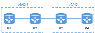
The topology will consist of a 2 x vMX running on the same Ubuntu host.
I will configure EVPN however EVPN is unfortunately not supported within a Logical System, so R2 and R3 will be the main routers on each vMX and will be my EVPN PEs.
R1 and R4 will be created as Logical System routers.
I will connect ge-0/0/1 and ge-0/0/2 on each of vMX back to back using a linux bridge and these interfaces will then be used to provide the interconnection between the main router and Logical System using VLANs. I could use LT interfaces but where is the fun in that.
ge-0/0/3 on vMX1 and vMX2 will be interconnected using a Linux virtio bridge on the host.
vMX2 instance setup
First things first, let’s get the second instance of vMX running. If you remember from my 1st vMX post there is a configuration file for the vMX instance. Running a second vMX instance is no different and has it’s own settings file. I will copy vmx1’s config file and use that as the basis for the vMX2.
mdinham@ubuntu:~/vmx-14.1R5.4-1$ cd config/
mdinham@ubuntu:~/vmx-14.1R5.4-1/config$ cp vmx.conf vmx2.conf
Now let’s have a look at what settings need to be changed in vmx2.conf
The vMX identifier is changed to vmx2. I am using the same host management interface for both vMX1 and vMX2 and no changes are needed to the images.
HOST:
    identifier                : vmx2   # Maximum 4 characters
    host-management-interface : eth0
    routing-engine-image      : "/home/mdinham/vmx-14.1R5.4-1/images/jinstall64-vmx-14.1R5.4-domestic.img"
    routing-engine-hdd        : "/home/mdinham/vmx-14.1R5.4-1/images/vmxhdd.img"
    forwarding-engine-image   : "/home/mdinham/vmx-14.1R5.4-1/images/vPFE-lite-20150707.img"
The external bridge can be used by both vMX1 and vMX2 so no need to change this setting. This is used to bridge the management interfaces on vMX to the host management interface defined above.
BRIDGES:
    - type  : external
      name  : br-ext                  # Max 10 characters
For the vRE and vPFE I will need to make some changes to console port, management ip address and MAC address. The MAC addresses taken from the locally administered MAC addresses ranges, so no problem to choose my own – taking care not to overlap with vMX1. Also, chose a console port number and management IP address that will not overlap with vMX1.
---
#vRE VM parameters
CONTROL_PLANE:
    vcpus       : 1
    memory-mb   : 2048
    console_port: 8603

    interfaces  :
      - type      : static
        ipaddr    : 192.168.100.52
        macaddr   : "0A:00:DD:C0:DE:0F"

---
#vPFE VM parameters
FORWARDING_PLANE:
    memory-mb   : 6144
    vcpus       : 3
    console_port: 8604
    device-type : virtio

    interfaces  :
      - type      : static
        ipaddr    : 192.168.100.53
        macaddr   : "0A:00:DD:C0:DE:11"
We also need to adjust the MAC addresses on each vMX2 interface.
---
#Interfaces
JUNOS_DEVICES:
   - interface            : ge-0/0/0
     mac-address          : "02:06:0A:0E:FF:F4"
     description          : "ge-0/0/0 interface"

   - interface            : ge-0/0/1
     mac-address          : "02:06:0A:0E:FF:F5"
     description          : "ge-0/0/0 interface"

   - interface            : ge-0/0/2
     mac-address          : "02:06:0A:0E:FF:F6"
     description          : "ge-0/0/0 interface"

   - interface            : ge-0/0/3
     mac-address          : "02:06:0A:0E:FF:F7"
     description          : "ge-0/0/0 interface"
vMX2 is now ready to be built. The same orchestration script that I used to create vMX1 is again used for vMX2, but this time I need to specify the configuration file.
Note: each time I use “vmx.sh” to perform stop/start operations on vMX2, I must specify the configuration file for vMX2.
The script will create the new vMX instance and automatically start it.
mdinham@ubuntu:~/vmx-14.1R5.4-1$ sudo ./vmx.sh -lv --install --cfg config/vmx2.conf
I’m now ready to connect to the console on vMX2. This is done the same way for vMX1 and vMX2, we simply reference the correct vMX instance when running the script.
mdinham@ubuntu:~/vmx-14.1R5.4-1$ ./vmx.sh --console vcp vmx2
--nesiac (ttyd0)
Login Console Port For vcp-vmx2 - 8603
Press Ctrl-] to exit anytime
--
Trying ::1...1R5.4 built 2015-07-02 08:01:42 UTC
Trying 127.0.0.1...
Connected to localhost.
Escape character is '^]'.


Amnesiac (ttyd0)

login:
If I look at the linux bridges the script automatically created you’ll see that another internal bridge is present to enable the RE and PFE communication on vMX2. The external bridge (management bridge) is shared by all vMX management interfaces.
mdinham@ubuntu:~/vmx-14.1R5.4-1/config$ brctl show
bridge name     bridge id               STP enabled     interfaces
br-ext          8000.000c2976a815       yes             br-ext-nic
                                                        eth0
                                                        vcp_ext-vmx1
                                                        vcp_ext-vmx2
                                                        vfp_ext-vmx1
                                                        vfp_ext-vmx2
br-int-vmx1     8000.525400866237       yes             br-int-vmx1-nic
                                                        vcp_int-vmx1
                                                        vfp_int-vmx1
br-int-vmx2     8000.5254006ec6d9       yes             br-int-vmx2-nic
                                                        vcp_int-vmx2
                                                        vfp_int-vmx2
virtio bindings
As I did in my vMX getting started post, for the Ethernet connectivity to the vMX I will be using KVM virtio paravirtualisation.
virtio bindings are flexible and can be used to map multiple vMX instances to a physical host interface, or to connect vMX instances or vMX interfaces together which we will be doing here. Linux bridges are used to stitch everything together.
At this point both vMX1 and vMX2 are running, but I need to create the virtio bindings to enable the communication between each MX.
For both vMX1 and vMX2 this is done in the same configuration file – config/vmx-junosdev.conf
I’ll create a link between vMX1 interfaces ge-0/0/1 and ge-0/0/2.
     - link_name  : vmx_link_ls
       endpoint_1 :
         - type        : junos_dev
           vm_name     : vmx1
           dev_name    : ge-0/0/1
       endpoint_2 :
         - type        : junos_dev
           vm_name     : vmx1
           dev_name    : ge-0/0/2
The same is done for vMX2
     - link_name  : vmx2_link_ls
       endpoint_1 :
         - type        : junos_dev
           vm_name     : vmx2
           dev_name    : ge-0/0/1
       endpoint_2 :
         - type        : junos_dev
           vm_name     : vmx2
           dev_name    : ge-0/0/2
Finally I will create a link between ge-0/0/3 on vMX1 and vMX2. I could use the same technique as shown above, but what if I wanted to connect more than 2 vMX together on the same Ethernet segment? It would be done like this with an additional bridge being defined and shared by each vMX.
     - link_name  : bridge_vmx_12
       endpoint_1 :
         - type        : junos_dev
           vm_name     : vmx1
           dev_name    : ge-0/0/3
       endpoint_2 :
         - type        : bridge_dev
           dev_name    : bridge_vmx12

     - link_name  : bridge_vmx_12
       endpoint_1 :
         - type        : junos_dev
           vm_name     : vmx2
           dev_name    : ge-0/0/3
       endpoint_2 :
         - type        : bridge_dev
           dev_name    : bridge_vmx12
Again the orchestration script vmx.sh is used to create the device bindings
mdinham@ubuntu:~/vmx-14.1R5.4-1$ sudo ./vmx.sh --bind-dev
Now let’s look at what bridges we have!
- br-ext – the external bridge for management traffic
- br-int-vmx1 – the internal bridge for vMX1 RE to PFE traffic
- br-int-vmx2 – the internal bridge for vMX2 RE to PFE traffic
- bridge_vmx12 – to enable the communication between ge-0/0/3 on vMX1 and vMX2
- virbr0 – unused as all vMX interfaces are defined
- vmx1_link_ls – connects ge-0/0/1 and ge-0/0/2 on vMX1
- vmx2_link_ls – connects ge-0/0/1 and ge-0/0/2 on vMX2
- vmx_link – connects ge-0/0/0 on vMX1 and vMX2 to eth1 on the host
mdinham@ubuntu:~/vmx-14.1R5.4-1$ brctl show
bridge name     bridge id            STP enabled     interfaces
br-ext          8000.000c2976a815    yes             br-ext-nic
                                                     eth0
                                                     vcp_ext-vmx1
                                                     vcp_ext-vmx2
                                                     vfp_ext-vmx1
                                                     vfp_ext-vmx2
br-int-vmx1     8000.525400866237    yes             br-int-vmx1-nic
                                                     vcp_int-vmx1
                                                     vfp_int-vmx1
br-int-vmx2     8000.5254006ec6d9    yes             br-int-vmx2-nic
                                                     vcp_int-vmx2
                                                     vfp_int-vmx2
bridge_vmx12    8000.fe060a0efff3    no              ge-0.0.3-vmx1
                                                     ge-0.0.3-vmx2
virbr0          8000.000000000000    yes
vmx2_link_ls    8000.fe060a0efff5    no              ge-0.0.1-vmx2
                                                     ge-0.0.2-vmx2
vmx_link        8000.000c2976a81f    no              eth1
                                                     ge-0.0.0-vmx1
                                                     ge-0.0.0-vmx2
vmx_link_ls     8000.fe060a0efff1    no              ge-0.0.1-vmx1
                                                     ge-0.0.2-vmx1
At this point vMX1 and vMX2 are ready to be configured.
EVPN Lab
EVPN is defined in RFC7432. It provides a number of enhancements over VPLS, particularly as MAC address learning now occurs in the control plane and is advertised between PEs using an MP-BGP MAC route. Compared to VPLS which uses data plane flooding to learn MAC addresses, this BGP based approach enables EVPN to limit the flooding of unknown unicast. MAC addresses are now being routed which in multi homed scenarios enables all active links to be utilised. Neat stuff. Also look up the Juniper Day 1 on EVPN.
I’ve already configured a base configuration on R2 and R3. Note I changed the chassis network-services mode to enhanced-ip from the vMX default of enhanced-ethernet.
root@R2# show | compare
[edit]
+  chassis {
+      network-services enhanced-ip;
+  }
+  interfaces {
+      ge-0/0/3 {
+          unit 0 {
+              family inet {
+                  address 192.168.23.2/24;
+              }
+              family mpls;
+          }
+      }
+      lo0 {
+          unit 0 {
+              family inet {
+                  address 2.2.2.2/32;
+              }
+          }
+      }
+  }
+  protocols {
+      mpls {
+          interface ge-0/0/3.0;
+      }
+      ospf {
+          area 0.0.0.0 {
+              interface lo0.0 {
+                  passive;
+              }
+              interface ge-0/0/3.0;
+          }
+      }
+      ldp {
+          interface ge-0/0/3.0;
+      }
+  }
Comms are up between vMX1 and vMX2
root@R2> ping 192.168.23.3 rapid
PING 192.168.23.3 (192.168.23.3): 56 data bytes
!!!!!
--- 192.168.23.3 ping statistics ---
5 packets transmitted, 5 packets received, 0% packet loss
round-trip min/avg/max/stddev = 2.031/2.253/2.805/0.281 ms

root@R2> show ospf neighbor
Address          Interface              State     ID               Pri  Dead
192.168.23.3     ge-0/0/3.0             Full      3.3.3.3          128    37

root@R2> show ldp neighbor
Address            Interface          Label space ID         Hold time
192.168.23.3       ge-0/0/3.0         3.3.3.3:0                14
Now I have reachability between R2 and R3 I can go ahead and add the required base config for EVPN.
Note: EVPN is unfortunately not supported within a Logical System so I am configuring EVPN on the main routers.
From Junos 14.1R4 the chained composite next hop features for EVPN will automatically be configured. Chained composite next hops are required for EVPN and allow the ingress PE to take multiple actions before forwarding.
root@R2> ...configuration routing-options | display inheritance defaults
autonomous-system 65000;
##
## 'forwarding-table' was inherited from group 'junos-defaults'
##
forwarding-table {
    ##
    ## 'evpn-pplb' was inherited from group 'junos-defaults'
    ##
    export evpn-pplb;
    ##
    ## 'chained-composite-next-hop' was inherited from group 'junos-defaults'
    ##
    chained-composite-next-hop {
        ##
        ## 'ingress' was inherited from group 'junos-defaults'
        ##
        ingress {
            ##
            ## 'evpn' was inherited from group 'junos-defaults'
            ##
            evpn;
        }
    }
}
We require the evpn and inet-vpn MP-BGP address families. Here I am configuring an iBGP peering with R3.
root@R2# show | compare
[edit]
+  routing-options {
+      autonomous-system 65000;
+  }
[edit protocols]
+   bgp {
+       group internal {
+           type internal;
+           local-address 2.2.2.2;
+           family inet-vpn {
+               unicast
+           }
+           family evpn {
+               signaling;
+           }
+           neighbor 3.3.3.3;
+       }
+   }
At this point the core configuration for EVPN is complete.
Logical Systems
My configuration gets a little more complicated here, because I need to create R1 and R4 as Logical Systems on my vMX. I will do this now.
Remember that ge-0/0/1 and ge0/0/2 have been connected back to back by the virtio bridge. I will use ge-0/0/1 as the interface on R2/R3 and ge-0/0/2 as the interfaces on the Logical System routers R1/R4.
root@R2# show | compare
[edit]
+ logical-systems {
+     R1 {
+         interfaces {
+             ge-0/0/2 {
+                 unit 100 {
+                     vlan-id 100;
+                     family inet {
+                         address 192.168.14.1/24;
+                     }
+                 }
+             }
+         }
+     }
+ }
[edit interfaces]
+   ge-0/0/2 {
+       vlan-tagging;
+   }
Not required for this lab, but if you wanted to create multiple Logical System routers on the same vMX this can of course be done. In the example below I have created two routers R5 and R6, they are linked together via ge-0/0/1 (R5) and ge-0/0/2 (R6) with vlan 56 being used as the VLAN ID for this point to point link. You can of course configure OSPF/BGP/MPLS etc directly between these routers. The configuration is defined in the appropriate logical system stanza.
logical-systems {
    R5 {
        interfaces {
            ge-0/0/1 {
                unit 56 {
                    vlan-id 56;
                    family inet {
                        address 192.168.56.5/24;
                    }
                }
            }
            lo0 {
                unit 5 {
                    family inet {
                        address 5.5.5.5/32;
                    }
                }
            }
        }
    }
    R6 {
        interfaces {
            ge-0/0/2 {
                unit 56 {
                    vlan-id 56;
                    family inet {
                        address 192.168.56.6/24;
                    }
                }
            }
            lo0 {
                unit 6 {
                    family inet {
                        address 6.6.6.6/32;
                    }
                }
            }
        }
    }
}
Working with Logical Systems is simple and commands can be entered in a couple of ways. Configuration can also be entered directly when the CLI is set to a Logical System.
root@R2> set cli logical-system R1
Logical system: R1

root@R2:R1> ping 192.168.14.1 rapid
PING 192.168.14.1 (192.168.14.1): 56 data bytes
!!!!!
--- 192.168.14.1 ping statistics ---
5 packets transmitted, 5 packets received, 0% packet loss
round-trip min/avg/max/stddev = 0.012/0.091/0.242/0.085 ms

root@R2:R1> clear cli logical-system
Cleared default logical system

root@R2> ping logical-system R1 192.168.14.1 rapid
PING 192.168.14.1 (192.168.14.1): 56 data bytes
!!!!!
--- 192.168.14.1 ping statistics ---
5 packets transmitted, 5 packets received, 0% packet loss
round-trip min/avg/max/stddev = 0.009/0.013/0.026/0.007 ms
Completing the EVPN configuration
I’m going to be configuring the EVPN VLAN based service. This requires a separate EVI per VLAN. An EVI is a an EVPN instance spanning across the PEs participating in a particular EVPN.
There isn’t too much to the configuration. I configure the interface facing R1, and then define the evpn routing-instance.
root@R2# show | compare
[edit interfaces]
+   ge-0/0/1 {
+       flexible-vlan-tagging;
+       encapsulation flexible-ethernet-services;
+       unit 100 {
+           encapsulation vlan-bridge;
+           vlan-id 100;
+       }
+   }
[edit]
+  routing-instances {
+      EVPN100 {
+          instance-type evpn;
+          vlan-id 100;
+          interface ge-0/0/1.100;
+          route-distinguisher 2.2.2.2:1;
+          vrf-target target:1:1;
+          protocols {
+              evpn;
+          }
+      }
+  }
Note: If you try to configure an evpn routing-instance on a logical system, you won’t see the option for evpn.
root@R2> set cli logical-system R1
Logical system: R1

root@R2:R1> configure
Entering configuration mode

[edit]
root@R2:R1# set routing-instances evpn instance-type ?
Possible completions:
  forwarding           Forwarding instance
  l2backhaul-vpn       L2Backhaul/L2Wholesale routing instance
  l2vpn                Layer 2 VPN routing instance
  layer2-control       Layer 2 control protocols
  mpls-internet-multicast  Internet Multicast over MPLS routing instance
  no-forwarding        Nonforwarding instance
  virtual-router       Virtual routing instance
  virtual-switch       Virtual switch routing instance
  vpls                 VPLS routing instance
  vrf                  Virtual routing forwarding instance
[edit]
Verification
Let’s see if I can ping across the EVI from R1 to R4.
root@R2> set cli logical-system R1
Logical system: R1

root@R2:R1> ping 192.168.14.4 rapid
PING 192.168.14.4 (192.168.14.4): 56 data bytes
!!!!!
--- 192.168.14.4 ping statistics ---
5 packets transmitted, 5 packets received, 0% packet loss
round-trip min/avg/max/stddev = 3.644/26.570/97.943/36.259 ms

root@R2:R1> show arp
MAC Address Address Name Interface Flags
02:06:0a:0e:ff:f6 192.168.14.4 192.168.14.4 ge-0/0/2.100 none
Excellent!
Now what does this look like from R2’s perspective, we see 2 BGP paths received.
root@R2> show bgp summary
Groups: 1 Peers: 1 Down peers: 0
Table          Tot Paths  Act Paths Suppressed    History Damp State    Pending
bgp.evpn.0
                       2          2          0          0          0          0
Peer                     AS      InPkt     OutPkt    OutQ   Flaps Last Up/Dwn State|#Active/Received/Accepted/Damped...
3.3.3.3               65000         93         94       0       0       36:29 Establ
  bgp.evpn.0: 2/2/2/0
  EVPN100.evpn.0: 2/2/2/0
  __default_evpn__.evpn.0: 0/0/0/0
Looking more deeply we can see MAC addresses in the EVPN100 table, both the directly attached device and also the device attached to R3.
root@R2> show route table EVPN100.evpn.0

EVPN100.evpn.0: 4 destinations, 4 routes (4 active, 0 holddown, 0 hidden)
+ = Active Route, - = Last Active, * = Both

2:2.2.2.2:1::100::02:06:0a:0e:ff:f2/304
                   *[EVPN/170] 00:03:27
                      Indirect
2:3.3.3.3:1::100::02:06:0a:0e:ff:f6/304
                   *[BGP/170] 00:03:27, localpref 100, from 3.3.3.3
                      AS path: I, validation-state: unverified
                    > to 192.168.23.3 via ge-0/0/3.0
3:2.2.2.2:1::100::2.2.2.2/304
                   *[EVPN/170] 00:20:27
                      Indirect
3:3.3.3.3:1::100::3.3.3.3/304
                   *[BGP/170] 00:18:38, localpref 100, from 3.3.3.3
                      AS path: I, validation-state: unverified
                    > to 192.168.23.3 via ge-0/0/3.0
Here we can see EVPN database and MAC table information.
root@R2> show evpn database
Instance: EVPN100
VLAN  MAC address        Active source                  Timestamp        IP address
100   02:06:0a:0e:ff:f2  ge-0/0/1.100                   Jul 28 17:11:14
100   02:06:0a:0e:ff:f6  3.3.3.3                        Jul 28 17:11:15

root@R2> show evpn mac-table

MAC flags       (S -static MAC, D -dynamic MAC, L -locally learned, C -Control MAC
    O -OVSDB MAC, SE -Statistics enabled, NM -Non configured MAC, R -Remote PE MAC)

Routing instance : EVPN100
 Bridging domain : __EVPN100__, VLAN : 100
   MAC                 MAC      Logical          NH     RTR
   address             flags    interface        Index  ID
   02:06:0a:0e:ff:f2   D        ge-0/0/1.100
   02:06:0a:0e:ff:f6   DC                        1048575 1048575
Local MAC addresses are being advertised from R2 to R3.
root@R2> show route advertising-protocol bgp 3.3.3.3

EVPN100.evpn.0: 4 destinations, 4 routes (4 active, 0 holddown, 0 hidden)
  Prefix                  Nexthop              MED     Lclpref    AS path
  2:2.2.2.2:1::100::02:06:0a:0e:ff:f2/304
*                         Self                         100        I
  3:2.2.2.2:1::100::2.2.2.2/304
*                         Self                         100        I
Here we can see detailed information about the EVPN routing instance.
root@R3> show evpn instance EVPN100 extensive
Instance: EVPN100
  Route Distinguisher: 3.3.3.3:1
  VLAN ID: 100
  Per-instance MAC route label: 299792
  MAC database status                Local  Remote
    Total MAC addresses:                 1       1
    Default gateway MAC addresses:       0       0
  Number of local interfaces: 1 (1 up)
    Interface name  ESI                            Mode             Status
    ge-0/0/1.100    00:00:00:00:00:00:00:00:00:00  single-homed     Up
  Number of IRB interfaces: 0 (0 up)
  Number of bridge domains: 1
    VLAN ID  Intfs / up    Mode             MAC sync  IM route label
    100          1   1     Extended         Enabled   299872
  Number of neighbors: 1
    2.2.2.2
      Received routes
        MAC address advertisement:              1
        MAC+IP address advertisement:           0
        Inclusive multicast:                    1
        Ethernet auto-discovery:                0
  Number of ethernet segments: 0
Summary
In this post I showed how multiple vMX can be configured and interconnected on the same Linux host. I also built a topology of 4 logical routers on the two vMX and used EVPN to demonstrate the capability of vMX.
I’ve also completed a VPLS lab with 5 x Logical System routers running on a single vMX. If you would like to see a post on this type of configuration please mention in the comments or tweet @mattdinham.
Thanks for reading 🙂
Matt. is license required for evpn? wondering what’s the limitation of VMX for lab testing without license.
thanks
Hi – thanks for reading the post 🙂
I created this lab and configured EVPN without applying a licence to vMX.
Also tested BGP and it would load around 32k BGP routes.
If you buy a licence, then I think it looks like this:
100M, 250M and 500M are limited to 50 VPN instances (both L2 and L3 VPN technologies), 128K RIB and FIB
1G Advanced 16 L3VPN instances, 250 EVPN/VPLS/L2VPN instances, 4M RIB
1G Premium 250 VPN (both L2 and L3)
Does changing network services mode actually work? I have tried and it keeps going back to Ethernet mode. I have noticed weird logs during boot mentioning network service mode is changing regardless if I have changed the mode or not:
configuration…Chassis control process:
Chassis control process: chassisd
Chassis control process: [edit]
Chassis control process: chassis
Chassis control process: WARNING: Chassis configuration for network services has been changed. A system reboot is mandatory. Please reboot the system NOW. Continuing without a reboot might result in unexpected system behavior.
Chassis control process:
Hi Steve, yes I see the same warnings and show chassis network-services does not seem to change from enhanced-ethernet.
I suspect it may be related to vMX license (I will have a licensed vMX soon so will be able to test again).
Try this – configure a vrf routing-instance and assign an interface. When you comment the change you will see this
root> show route
error: the routing subsystem is not running
And in the logs and rpd error: “Only loopback interface is supported under vrf routing instances in triton mode”
Triton mode refers to ethernet services mode. If you reboot though, it does work (fails again at commit)
Hi, I got this resolved by adding license.
thank you,
Hi, is it possible to have two REs in vMX to test some of the redundancy options in juniper ?
Hi – thanks for reading the post. No, I don’t think we can do this currently on vMX
Would definitely love a post on your vMX VPLS lab.
Hello,
What about new vmx 15.1? Any one tested it?
From what I read it is not possible to run it on a single VM with fpc emulated as in 14.1 ver.
Please advise.
Thanks
Hi,
I just tried to deploy vMx using same scenario. When 2 VMXs are deployed. I donot see any interfaces of VMx. ge-0/0/0, ge-0/0/1, ge-0/0/2 etc.
Further to add, ospf neighbor ships are also not established.
Could you kindly help out.
Regards
Usman Khan
It sounds like the VFP has not started or has crashed – try attaching to the console immediately after the VFP starts and looks for error messages / crash info
I tested a recent (at this time of writing) version of vMX, namely the 15.1F4.15. I’ve the same issue about the network services mode. If it set the mode to ‘enhanced-ip’ it actually still run with the default, Enhanced-Ethernet mode, even after a RE/VCP reboot.
I’m also wondering if the multiservice (ms) interfaces are supported. I do see the tunnel service and the service interfaces are both available and seems to work fine. However for features like NAPT44 to work, it looks like a ms interface is mandatory.
Hi – if you apply the license at https://www.juniper.net/us/en/dm/free-vmx-trial/ then then network services mode will automatically change 🙂